From simple text and images
to precise 3D CAD files

One line of description or a single image becomes a part-separated 3D model. Keep editing with prompts and millimeter parameters, convert to STEP and DXF, and drop the result straight into the CAD tools you already use. Polygon optimization included.

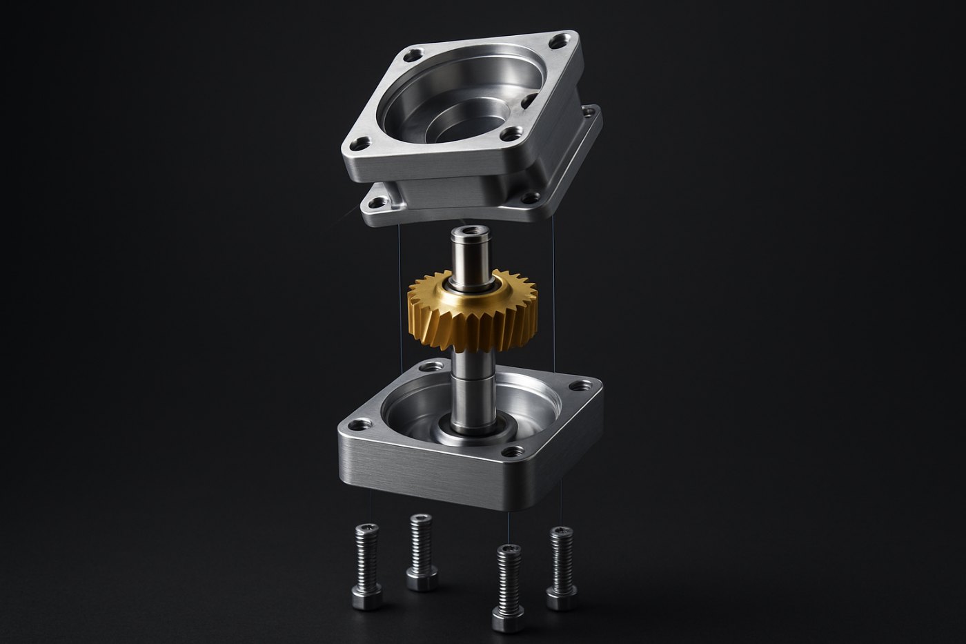
Exploded view of a part-separated gearbox assembly
Partners we have worked with
NVIDIA Inception Samsung C-Lab Lotte Ventures MCM ASICS SPYDER Dream International DREAM PLASTIC INNOX
Why

Where your design hours
are actually going

Repetitive modeling for concept mockups, prep work for design reviews, manual reverse-engineering of scans and images. That is preparation, not judgment. VRINGON CAD reduces this stage to minutes.

Product

One flow, four steps

01

Generate

A one-line prompt or a single image or sketch. The AI writes a millimeter-level spec and builds the 3D model from it.

02

Part separation

Housings, covers, and fasteners come out as an assembly structure from the start. Verify instantly with the explode and assemble motion.

03

Edit

Follow-up prompts like "lower the height to 160 mm", millimeter parameters, and per-part materials.

04

Convert and optimize

Convert to STEP (AP214) and DXF, and auto-reduce polygons to fit the use case before export.

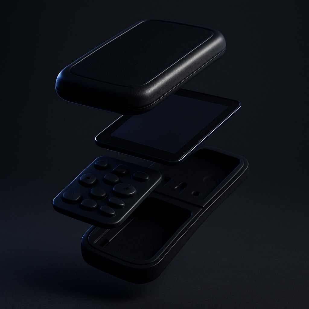
A device separated into parts
Parts, not a single blob

The output is a part tree, not one merged mesh. Select, move, and re-material parts individually, with explode and assemble animation built into the viewer.

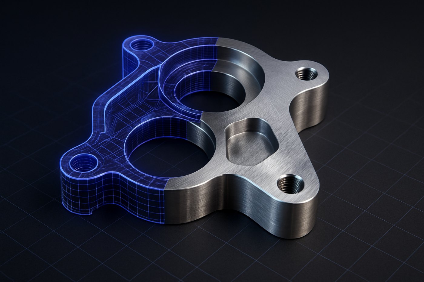
CAD geometry transitioning from wireframe to solid
Hand over CAD, not meshes

Convert to STEP (AP214) with per-part solids and layer-separated DXF. Opens directly in SolidWorks, CATIA, NX, and Creo.

Follow-up prompt editing

"Three ribs, 3 mm walls" translates into parameter changes and applies instantly. Select a part first and the edit scopes to that part.

Parametric editing

Every dimension is a millimeter parameter. Move a slider and fillets and bolt patterns recompute together.

Automatic polygon optimization

Three tessellation presets plus a reduction slider produce anything from lightweight viewer meshes to full-resolution data from one model.

Drawing and sketch input

Upload a dimensioned 2D drawing and the callouts — Ø, R, t and each projected view — are transcribed into the 3D model. Hand sketches follow the silhouette and proportions.

Links and joints, inferred

Parts are separated, mating faces measured, and each connection resolved to a revolute, prismatic or fixed joint. Travel limits come from actually sweeping the joint until it interferes with its parent.

USD, URDF and MJCF export

Collision shapes and mass properties are generated separately from the visual mesh, and only assets that pass the simulation sweep and format round-trip ship — with a readiness score attached.

Security

Your data never leaves
your own servers

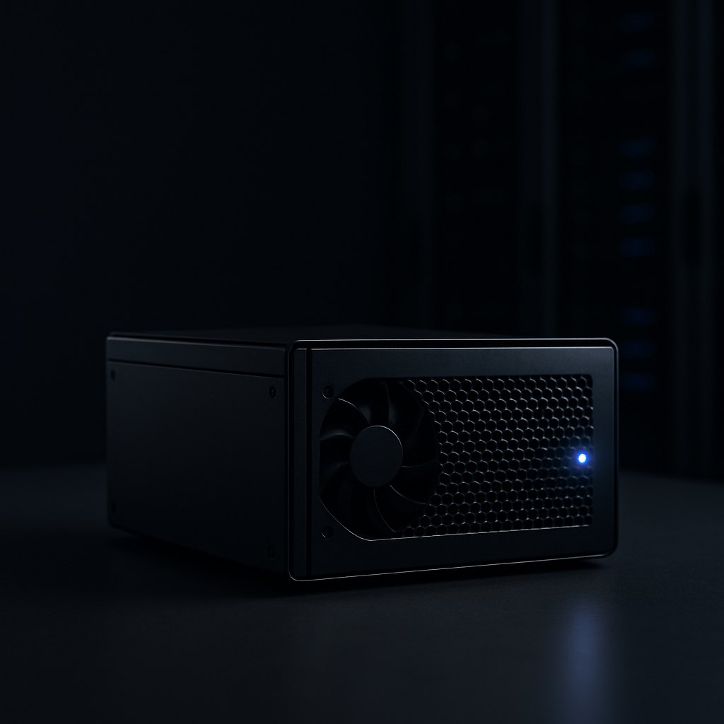
VRINGON CAD is on-premise software installed on your infrastructure. Generation, editing, and conversion all run inside your network, including fully air-gapped configurations. Your infrastructure, your rules.

  • Operated on ISO/IEC 27001 and ISO/IEC 42001 processes
  • Customer data is never used for training, stated in the contract
  • SSO/LDAP integration and full audit logging
An on-premise GPU server
Integration

It sits on top of your CAD stack

VRINGON CAD does not replace your tools. It is the front end that creates initial geometry and hands it over in standard formats that open in SolidWorks, CATIA, NX, Creo, and Fusion.

STEP AP214

Standard exchange format with per-part solids preserved, for CAD, CAM, and CAE.

DXF

Layer-separated format for drawing systems.

GLB · OBJ · STL

Mesh formats for visualization, collaboration, and 3D printing, with the part hierarchy intact.

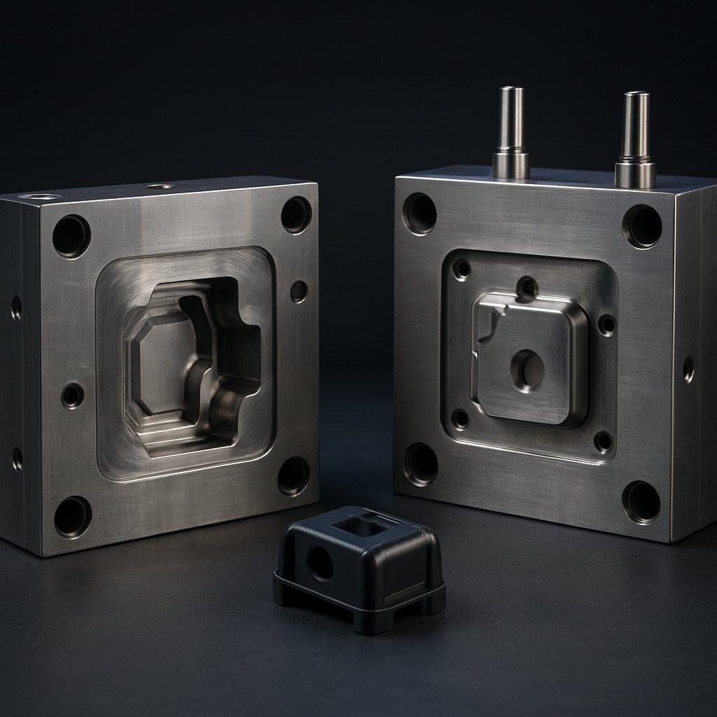
An injection mold
Beyond software

If design is not the end of the road

For customers who need it, we also support mold design review, injection process optimization, and connections to verified manufacturing partners, so the data you create in software carries through to production. This is an optional service.

Contact us
FAQ

Frequently asked questions

Can it be installed on our own servers?

Yes. On-premise installation on your servers is the default. After installation, all generation and conversion runs inside your infrastructure. A private cloud (VPC) setup is also available on request.

Is any of our design data sent outside?

In an on-premise installation, design data never leaves your network. We do not access customer data and never use it for model training. This is stated in the contract.

Do you hold ISO certifications?

We develop and operate on processes based on ISO/IEC 27001 for information security and ISO/IEC 42001 for AI management. Scope details and security controls are available as a security review package.

Does it work in an air-gapped network?

Yes. It is designed to run without external connectivity, and models and updates are delivered as offline packages following your security procedures.

How does it integrate with our existing CAD tools?

Exports use standard formats such as STEP and DXF that open directly in SolidWorks, CATIA, NX, and Creo. It is a front-end tool that creates initial geometry, not a replacement for your CAD.

Who owns the generated data?

All rights to geometry generated with VRINGON CAD belong to the customer. We claim no rights and place no restrictions on commercial use, provided your inputs do not infringe third-party rights.

What server capacity do we need?

You can start with a single GPU server (for example an RTX 4090 class or A100/H100). Tell us your usage scenario and we will size a recommended configuration; existing in-house GPU servers can be used.

How does a pilot work?

We run a pilot on your actual design tasks: requirements review, installation, task execution, and a results review. The pilot report includes time spent and output quality; duration and terms depend on scope.
See it for yourself

Try the full flow with a demo account, or ask for a pilot scoped to your own design tasks.

Try the demo Contact us